SGMKtiny
SGMK tiny
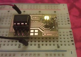
easy to use on breadboards with onboard connected ISP port. see general info about Hands On AVR
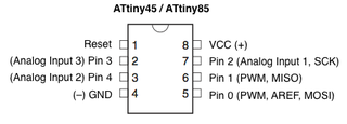
Pin Layout
v0.6:
v0.5
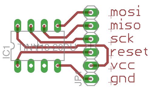
Another proposal for the SPI connector
Personally I find the "standard" AVR 6pin ISP connector very cumbersome
- not easy to route around it
- very small pads
- difficult to remember what pin is what
- without the correct cable with molex connector you're fucked
So I started to design all my boards that need a ISP connector like this:
GND | VCC | RESET | SCK | MISO | MOSI all in one row.
The advantage is that it's the same pinout like the bigger ATMEGAs, where you can pull out the ISP just straight like this: gnusb-procreation
Mask
Code Examples
programming the attiny85 with the arduino IDE
CrossPack development environment for Atmel’s AVR® microcontrollers running on Apple’s Mac OS X
Random noise generator
first set the clock divider to 8MHz
clock divided by 8 (1Mhz, as delivered) -U lfuse:w:0x62:m -U hfuse:w:0xdf:m -U efuse:w:0xff:m
clock not divided (8Mhz) avrdude -b 19200 -c usbtiny -p t85 -U lfuse:w:0xe2:m -U hfuse:w:0xdf:m -U efuse:w:0xff:m
/* Pseudo-Random Bit Sequence Generator                     2009-11-25 */
/* Copyright (c) 2009 John Honniball, Dorkbot Bristol                  */

/*
 * For a discussion of PRBS generators, see The Art Of Electronics, by
 * Horowitz and Hill, Second Edition, pages 655 to 660. For more info
 * on Linear Feedback Shift Registers, see Wikipedia:
 *   http://en.wikipedia.org/wiki/Linear_feedback_shift_register
 * For the actual shift register taps, refer to this article on noise
 * generation for synthesisers:
 *   http://www.electricdruid.net/index.php?page=techniques.practicalLFSRs
 */

// Choose the same pin as the "Melody" example sketch
int speakerPin = 0;

int potiPin = 1;

unsigned int analogValue;

int samplingDelay;

unsigned long int reg;

void setup ()
{
  // Serial setup for debugging only; slows down the program far too much
  // for audible white noise
  //Serial.begin (9600);

  // Connect a piezo sounder between Ground and this pin
  pinMode (speakerPin, OUTPUT);


  // Arbitrary inital value; must not be zero
  reg = 0x551155aaL;
}


void loop ()
{
  unsigned long int newr;
  unsigned char lobit;
  unsigned char b31, b29, b25, b24;

  // Extract four chosen bits from the 32-bit register
  b31 = (reg & (1L << 31)) >> 31;
  b29 = (reg & (1L << 29)) >> 29;
  b25 = (reg & (1L << 25)) >> 25;
  b24 = (reg & (1L << 24)) >> 24;

  // EXOR the four bits together
  lobit = b31 ^ b29 ^ b25 ^ b24;

  // Shift and incorporate new bit at bit position 0
  newr = (reg << 1) | lobit;

  // Replace register with new value
  reg = newr;

  // Drive speaker pin from bit 0 of 'reg'
  digitalWrite (speakerPin, reg & 1);

  // Display 'reg' in the serial console for debugging only
//  Serial.println (reg, HEX);
  samplingDelay = 1 + (2*(analogRead(potiPin)>>0));
  // Delay corresponds to 20kHz, but the actual frequency of updates
  // will be lower, due to computation time and loop overhead
  delayMicroseconds (samplingDelay);

  // If the above delay is increased to a few tens of milliseconds,
  // and the piezo sounder is replaced by an LED and a suitable series
  // resistor, a randomly flashing light will result. Several LEDs
  // could be driven from various bits of the shift register.
}


from [http://tziteras.blogspot.com/2009/11/green-noise-experiment.html John Honnibal]
Software Serial works an an ATiny85
important configure the ATiny85 to run on 8Mhz
avrdude -b 19200 -c usbtiny -p t85 -U lfuse:w:0xe2:m -U hfuse:w:0xdf:m -U efuse:w:0xff:m
/*
  Blink
  Turns on an LED on for one second, then off for one second, repeatedly.

  This example code is in the public domain.
 */

// Pin 13 has an LED connected on most Arduino boards.
// give it a name:
int led = 13;

// the setup routine runs once when you press reset:
void setup() {
  // initialize the digital pin as an output.
  pinMode(led, OUTPUT);
}

// the loop routine runs over and over again forever:
void loop() {
  digitalWrite(led, HIGH);   // turn the LED on (HIGH is the voltage level)
  delay(1000);               // wait for a second
  digitalWrite(led, LOW);    // turn the LED off by making the voltage LOW
  delay(1000);               // wait for a second
}
Software Serial to talk with pd
Code for Aruino
/*
  Software serial multple serial test

 The circuit: not sure with attiny, what is rx and what tx...
 * RX is digital pin 1 (connect to TX of other device)
 * TX is digital pin 0 (connect to RX of other device)

 Note:
 Not all pins on the attiny85 support change interrupts,
 so only the following can be used for RX/TX:
 0, 1

 This example code is in the public domain.

 */

#include <SoftwareSerial.h>

int sensorPin = 1; // select the analog input pin for the potentiometer ADC1 = PB2
int sensorValue = 0;  // variable to store the value coming from the sensor


SoftwareSerial mySerial(0, 1); // RX, TX

void setup()
{
  // Open serial communications and wait for port to open:

  // set the data rate for the SoftwareSerial port
  mySerial.begin(38400);
  mySerial.println("Hello, world?");
}

void loop() // run over and over
{

  sensorValue = analogRead(sensorPin);

  mySerial.print("T ");
  mySerial.print((sensorValue), DEC);
  mySerial.println();
  delay(2);

  /* this is kinda serial echo to check if it can receive... not yet tested in detail

  if (mySerial.available())
    mySerial.write(mySerial.read());

  */
}
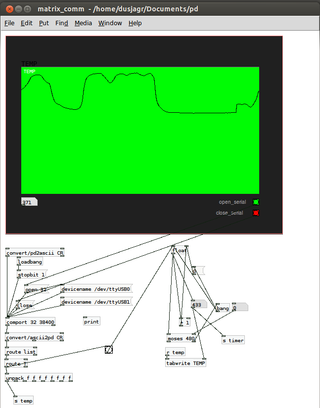
pd patch
download: File:SGMKtiny 2 pd-logger.zip
the serial port in pd needs to be changed according to your OS and serial interface


